This will (hopefully) be the last post about geometry and the Mesh-API, before we can start with the actual generation algorithms.
We’ve already defined a basic data structure for our geometry, implemented algorithms to traverse it and, in the last post, constructed a spherical Delaunay triangulation of random points, distributed evenly on a sphere.
So, the only part of the API that is still missing are functions to modify existing meshes. The three fundamental operations we’ll define for this are:
class Mesh {
  public:
	// ...

	void   flip    (Edge e);
	Edge   split   (Edge e, float split_point);
	Vertex collapse(Edge e, float join_point);
};
Edge Flip
The first of the three operations is the edge flip, that we’ll need later to restore the Delaunay condition of our mesh after vertices have been moved[1].
The effect of an edge flip is relatively straightforward. It just takes the edge, that is passed to it, and rotates it counterclockwise in the quad formed by the four surrounding vertices, as seen below:

flip(e)What we’ve ultimately done here is we removed the passed edge, to transform the two neighboring faces into a quad, and then created a new edge between the previously unconnected vertices to split it into two triangles again. From this, we also see that we can’t flip edges at the boundary of our mesh, since those only have a single “real” face.
Our implementation is further simplified by the fact that we don’t need to handle multiple cases, like did for add_face(). The reason is that there are only two possible ways to split a quad, which means the result is always unambiguous, regardless of which part of a quad-edge we pass as the argument. That means flip(e), flip(e.rot()), flip(e.sym()) and flip(e.inv_rot()) are all equivalent, and we can just normalize the input with e = e.base() and ignore all other cases, like flipping dual edges.
As always, there are two parts to this operation: Updating the primal mesh and its dual counterpart:
Primal Mesh
The update of the primal mesh is pretty straightforward. We just need to remove e and e.sym() from their old and add them to their new edge-rings.
Because we need to traverse the mesh during our modification, we have to be careful that we only override the data after we’ve read the required information. Therefore, we have to load and cache all values before we can write the new values to the Mesh member variables. So to make our lives easier and the code more readable, we use new_origin_next to memorize the new values and only apply them at the end using a simple class like this:
template <typename Value, std::size_t N>
class Edge_changes {
  public:
	// Array-Access-Operator reserves space for the new value
	//   and returns a reference to it
	Value& operator[](Edge e) {
		assert(next_idx_ < int(new_values_.size()));
		auto& e = new_values_[next_idx_++];
		e.first = e.index();
		return e.second;
	}

	// Apply the recorded changes to the given vector
	void apply(std::vector<Value>& out) {
		for(int i = 0; i < next_idx_; i++) {
			auto&& [index, val] = new_values_[i];
			out[index]          = val;
		}
	}

  private:
	std::array<std::pair<uint32_t, Value>, N> new_values_;
	int                                       next_idx_ = 0;
};

// Later instanciated with
auto new_origin_next = Edge_changes<Edge, 6>{};
This allows us to write the following code, to update all affected primal edges:
// Remove e and e.sym() from their current edge-rings
new_origin_next[e.origin_prev(mesh)]       = e.origin_next(mesh);
new_origin_next[e.sym().origin_prev(mesh)] = e.sym().origin_next(mesh);

// Add e to its new edge-ring
new_origin_next[e.dest_next(mesh)] = e;
new_origin_next[e]                 = e.origin_prev(mesh).sym();

// Add e.sym() to its new edge-ring
new_origin_next[e.origin_next(mesh).sym()] = e.sym();
new_origin_next[e.sym()]                   = e.dest_prev(mesh);

// ...

// Check if the original origin/dest vertices referenced the flipped edge
//   and set them to one of the remaining edges, if required
if(vertex_edges_[e.origin(mesh)] == e)
	vertex_edges_[e.origin(mesh)] = e.origin_next(mesh);
if(vertex_edges_[e.dest(mesh)] == e.sym())
	vertex_edges_[e.dest(mesh)] = e.sym().origin_next(mesh);

// Update the origin
primal_edge_origin_[e.index()] = e.origin_prev(mesh).dest(mesh);
primal_edge_origin_[e.sym().index()] = e.origin_next(mesh).dest(mesh);

// Apply the changes
new_origin_next.apply(primal_edge_next_);
Dual Mesh
Updating the dual mesh might look more complex at first because the flip also changes which faces are neighboring each other, but it’s actually simpler, because the edge-rings around faces are much more restricted. Since every face has exactly three outgoing edges and all flips are identical, we can just look at our diagram and see that we only need to swap two dual edges from the rings around e.left() and e.right().
flip(e). The dual edge de1 has been moved to the left and de2 to the right face, after e.rot() and e.inv_rot() respectively.// Move edge from left face to right face
const auto edge_from_left = e.inv_rot().origin_next(mesh);
const auto edge_from_left_prev = e.rot().origin_prev(mesh);
new_dual_origin_next[edge_from_left] = e.rot();
new_dual_origin_next[e.rot()] = edge_from_left_prev;
new_dual_origin_next[edge_from_left_prev] = edge_from_left;
// Move edge from right face to left face
const auto edge_from_right = e.rot().origin_next(mesh);
const auto edge_from_right_prev = e.inv_rot().origin_prev(mesh);
new_dual_origin_next[edge_from_right] = e.inv_rot();
new_dual_origin_next[e.inv_rot()) = edge_from_right_prev;
new_dual_origin_next[edge_from_right_prev) = edge_from_right;
// ... Update the primal mesh, as seen above ...
// Set the edges for the modified faces to one of the edges
face_edges_[e.left(mesh)] = e;
face_edges_[e.right(mesh)] = e.sym();
// Update the origin
dual_edge_origin_[edge_from_left.index()] = e.right(mesh);
dual_edge_origin_[edge_from_right.index()] = e.left(mesh);
// Apply the changes
new_dual_origin_next.apply(primal_edge_next_);
Edge Split and Collapse
One of the key advantages of representing our map as a triangle mesh, is that we can dynamically add/remove vertices to change the local resolution of our data. That means that we can use far fewer vertices in the middle of the ocean, where we don’t care about most terrain features, and use that storage for the parts that actually interest us instead.
To achieve this, we need two operations, one to add a new vertex at a given point and one to remove it again:[2]
Edge split(Edge e, float split_point): Takes an edge and a position on this edge [3] and splits the edge into two new edges, creating a new vertex at the given position and inserting edges and faces left/right of the edge, as required. The returned value is the new half of the split edge, pointing from the new vertex to the original destination.[4]Vertex collapse(Edge e, float join_point): Takes an edge and a position on it and collapses the edge, merging theorigin()anddest()into the specified location, as well as merging itsleft()/right()faces and their supporting edges.
As can be seen in the following image, we can interpret the operations as each other’s inverse.
Executing split(e, 0.25f) transforms the left mesh into the right one, inserting a new vertex — 25% along the way between the origin and destination of e —, two faces (FL and FR) and three quad-edges.
Executing collapse(e', 1.f) reverses this operation. The edge e’ is removed and its origin and destination are collapsed into a single vertex, that keeps the position of the destination (100% along the way from origin to destination).
While the implementation is a bit more intricate because we have more edges to consider, it follows the same procedure as flip(), i.e. connect the edges into valid edge-rings. Thus, I won’t go into too much detail here and focus on the preconditions and how deletions are handled, instead.
Preconditions for split()
The precondition of split() is quite simple — simpler even than for flip() — because it works on any edge with at least one face, which includes boundary edges. That is also the one special case we need to handle in the implementation: Are both faces present or are we splitting a boundary edge and the left/right face is missing.
Preconditions for collapse()
The situation for collapse() is quite different, however. Although, it could also function with any valid edge with at least one face, collapsing some edges might create invalid meshes. What all of these invalid cases have in common, is that collapse() would have to collapse more than the left/right faces, or it would leave unconnected edges/vertices behind. So, to detect them and avoid creating these corrupted meshes, there are two conditions we need to check first.
1. The Link Condition
The first thing we have to check is that the edge we want to collapse satisfies the link condition, defined in the 1998 paper “Topology Preserving Edge Contraction” by Dr. Tamal Dey et al, that guarantees that our manifold mesh will still be manifold after the collapse().
Its formal definition is, given the edge between vertices and :
Put simply, this means that every vertex that is connected to both and also has to be part of the face on the left or right side of . When put like this, we can also see the problem, that would arise if we ignored this condition: After we collapsed , there would be multiple distinct edges between the same two vertices, and .
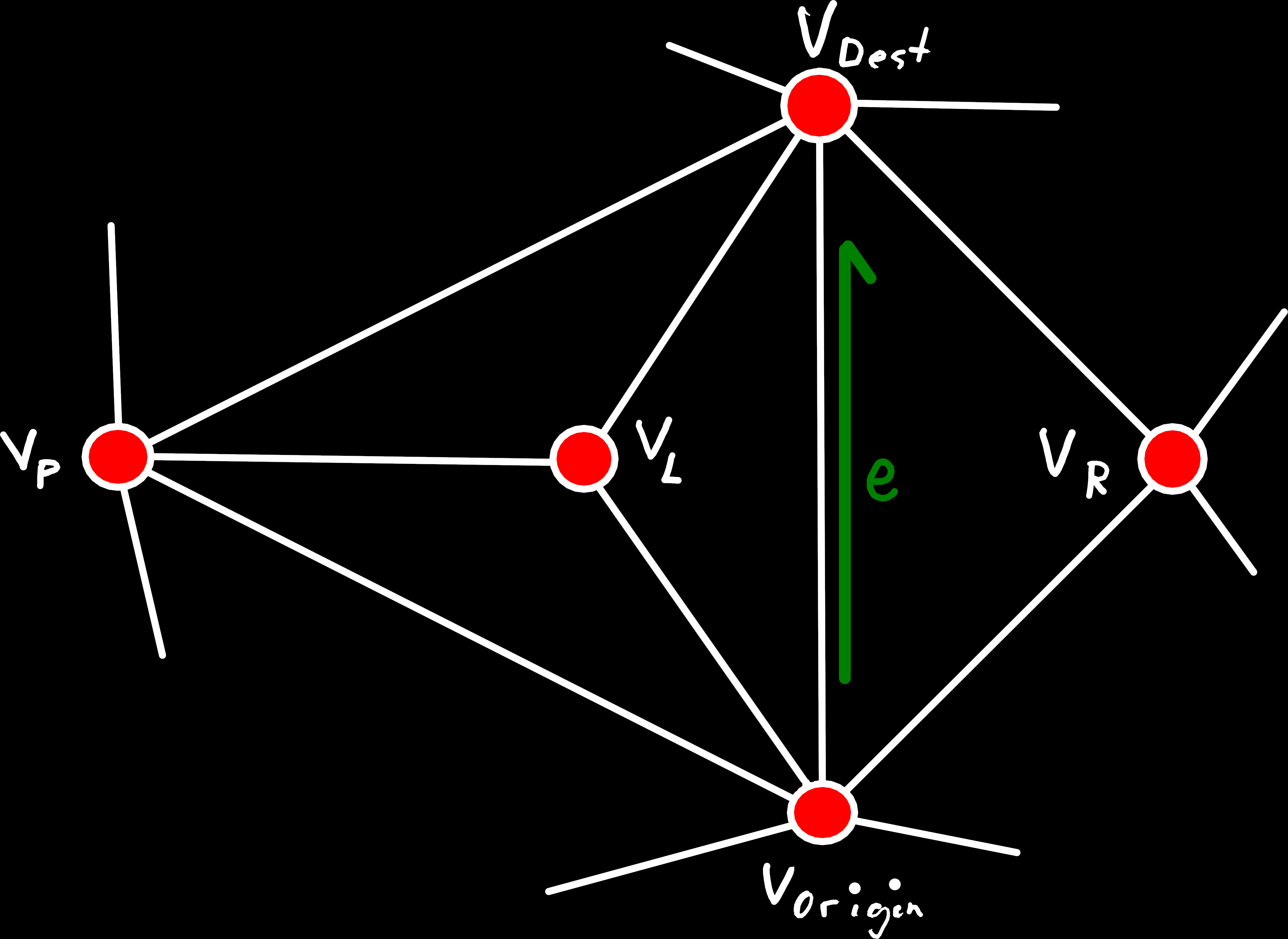
An example of an edge that doesn’t satisfy the link condition. The origin and destination of e are both connected to the vertex VP, which means the intersection of their one-rings contains the vertex VP, that is missing in the one-ring of e.
This means that we would have to also collapse some of the edges and faces around VP or produce a non-manifold mesh. Which is why this case is forbidden.
To check this condition, we can just iterate over the edge-ring around e.origin() and check if one of its neighboring vertices is also a neighbor of e.sym(). For this, we can utilize the Edge::origin_ccw() method, that returns a range of all edge in the origin-edge-ring, and the std::find_first_of algorithm, that tries to find the first matching element between two ranges. Of course, when iterating over the edge-rings we have to skip the first element, which is e itself. But we also need to skip the edge after that, if there is a face on that side of e because these edges are still part of the left/right face.
// Iterator ranges over the two edge-rings, starting from the edge after e (the edge we are collapsing)
// We also need to skip the vertex of the neighboring face, if there is one
const auto origin_edges = e.origin_ccw(mesh).skip(left ? 2 : 1);
const auto dest_edges   = e.sym().origin_ccw(mesh).skip(right ? 2 : 1);

// Check if there is an edge in the two ranges that share a common destination vertex
const auto iter = std::find_first_of(origin_edges.begin(),
                                     origin_edges.end_iterator(),
                                     dest_edges.begin(),
                                     dest_edges.end_iterator(),
                                     [&](Edge oe, Edge de) { return oe.dest(mesh) == de.dest(mesh); });

if(iter != origin_edges.end()) {
	// If there is such an edge the link condition is not satisfied
	yggdrasill::make_error(out_error, YGDL_ERROR_CODE_MESH_CORRUPTION, [&] {
		return "The link-condition is not satisfied for the edge passed to collapse()";
	});
	return no_vertex;
}
2. Vertices Shared by Unconnected Faces
While we can find most problematic cases by checking the link condition, there are still some we need to check separately, that are caused by our less restrictive mesh definition (e.g. unconnected sub-meshes, faces connected by only one vertex, unclosed meshes, …).
One of these is the “forbidden case” we excluded in add_face(), but now coming from the opposite direction. That is, we can’t collapse an edge if that would result in a vertex that is shared by multiple unconnected faces.
We can identify this case by checking if there are multiple boundary edges originating from e.origin() or e.dest() that are missing a face on the same side. Coincidentally, this also catches another minor error-case: When we collapse the last face of an unconnected sub-mesh, we would leave behind vertices without edges.
if(e.left(mesh) != no_face && e.right(mesh) != no_face) {
	// We only need to check this, if e is not already a boundary edge

	// We want to check if there are any edges in the given range, that don't have a right face
	auto has_right_boundary = [&](const auto& edge_range) {
		return std::any_of(edge_range.begin(), edge_range.end_iterator(),
		                   [&](Edge e) {return e.right(mesh) == no_face;} );
	};

	// ... and we want to check if that is the case around both the origin and destination of e
	if(has_right_boundary(e.origin_ccw(mesh)) && has_right_boundary(e.sym().origin_ccw(mesh))) {
		yggdrasill::make_error(out_error, YGDL_ERROR_CODE_MESH_CORRUPTION, [&] {
			return "Requested edge collapse would cause a corrupted mesh (multiple unconnected faces "
			       "on the same vertex) or a dangling vertex";
		});
		return no_vertex;
	}

} else if(e.left(mesh) == no_face && e.right(mesh) == no_face) {
	// The edge e is not part of any faces, which means the initial mesh is not valid to begin with
	yggdrasill::make_error(out_error, YGDL_ERROR_CODE_MESH_CORRUPTION, [&] {
		return "Corrupted mesh. The edge that should be collapsed is not part of a triangle";
	});
	return no_vertex;
}
Handling Deletions
Although, we now know how our data structure needs to change on split() and collapse(), there is one point we glossed over, which we briefly touched on when we first defined our mesh structure: Deleting elements of our mesh (vertices, faces and edges)
As we have seen above, collapsing an edge effectively deletes it, as well as its destination, bordering faces and some of their edges. But that is a problem because we can’t just directly delete part of our Mesh structure since we store all data of our elements in continuous vectors. So if we would just delete e.g. an edge from this structure, we would need to move all following values to close the gap and keep everything contiguous. However, that would not just be extremely inefficient for larger meshes, but also disturb our IDs. Remember that the ID of an element is also the index in the corresponding data-vector[5]. So if the index would change, that in turn would also change its ID, which we use everywhere to reference it. Which means we can’t do that and need an alternative solution.
Luckily, we already reserved one special ID for each of the element types, to represent a missing or invalid element (no_edge/no_vertex/no_face), which we can utilize now. So, when we have to delete an element, we will instead memorize its ID in a vector (called a free-list) and set all its values in the Mesh to this invalid state. And then when we later need to create new vertices, edges or faces, we can check this free-list first before allocating new storage, to fill in these “holes” the deletions left behind.
Of course, if we never really delete elements but just mark them as deleted, we must take care that they are never referenced or returned from any of our function. Following the algorithm outlined above, there already should never be any part of the mesh that references the vertices/edges/faces that were deleted, since these references were overridden by new values. So, the traversal operations should already work as expected, without any further work from our part. But where we need to do extra work is when we iterate over all vertices/faces/edges in the mesh. These operations would normally just iterate over all indices and return the corresponding IDs. Thus, we must add an extra check in the iterator, that reads one of the elements values from Mesh and checks whether it is set to a valid value.
Although, this means extra work on a relatively common operation, a linear read and comparison of 32-Bit integers should not impact us much[6]. Hence, at least for the expected use-case, where meshes don’t shrink over time[7], this should be pretty efficient.
Handling Topological Changes in Data Layers
Before we can (finally) close this chapter, there is one last aspect that deserves attention: How the data layers react to changes
As already mentioned, we’ll store all our data in layers that bind values of various types to parts of our mesh (vertices, faces and directed or undirected edges of the primal/dual mesh). So, when we modify the mesh itself, that will obviously affect the layer values for elements we added or deleted. But it might also invalidate information that was used to compute the values, e.g. if we flip() an edge no parts of the mesh are deleted, but some edges will be connected to entirely different vertices.
Hence, we’ll need a way to automatically modify layers if the mesh is changed, which is actually one of the reasons why we’ve defined the overarching World structure that contains both the mesh and all layers. So, when one of the modification operations of the mesh is called, we can just access the layers through our parent World, lock them for modification and apply any necessary changes to them.
Of course, that begs the question of what changes would be necessary. When we modify the mesh, we already know which parts of the mesh will be affected in what way. And through the World class and the Layer_info objects stored there, we can also determine which layers contain values that are linked to these affected elements. But the decision how values should be changed depends on the semantics of the concrete layer, which we’ll store in the Layer_info as two enumerations, one for each major type of topological change[8].
Deletion and Modification
The first (and easier) of these two covers the case when data is completely invalidated. Either because the part of the mesh that is referenced has been deleted or because the origin()/dest() of an edge changed. And the enum that describes the possible reactions is:
enum class On_mesh_change {
	keep,            // The value is not changed
	reset_affected,  // The value is reset to its initial value (normally 0)
	reset_all,       // ALL values of the layer are reset
	remove_layer     // The layer is deleted entirely
};
Creation and Merging
The second enumeration is a tad more complicated because it’s not used for invalidated or removed elements, but to calculate entirely new values.
This one is used every time a new element is inserted (new vertex, faces and edges) by split(), to interpolate its value based on its two neighbors[9], or when collapse() merged the two vertices of an edge into one[10]:
enum class Interpolation {
	dont_care,
	reset_affected,
	reset_all,
	remove_layer,
	keep_src,
	keep_dest,
	lerp,
	slerp,
	min_value,
	max_value,
	min_weight,
	max_weight
};
Because the behavior might not be obvious from their names alone, it’s perhaps better to show what their result would be for different inputs[11]:
And finally, here are some examples that show how this functionality will be used in practice:
// The layer that stores the vertex positions.
// Since all points have to be located on the surface of a sphere,
//   the interpolation has to make sure that they stay there
constexpr auto position_info  = Layer_info<Vec3, Layer_type::vertex>("position")
								.interpolation(Interpolation::slerp)
								.on_mesh_change(On_mesh_change::reset_affected);

// Each vertex is also assigned to a specific tectonic plate, by giving it an ID.
// Since we can't interpolate between IDs, we instead pick the one of the nearest vertex
constexpr auto layer_plate_id = Layer_info<std::int32_t, Layer_type::vertex>("plate_id")
								.interpolation(Interpolation::max_weight)
								.on_mesh_change(On_mesh_change::reset_affected);

// We also need to memorize the distance between sub-plates/vertices.
// These are assigned to the edges between vertices (independent of their direction).
// But if the topology changes we can't recompute them with the logic outlined above,
//   so instead they are reset to a known value (-1.0) and recomputed as needed.
constexpr auto layer_distance = Layer_info<float, Layer_type::edge_primal>("plate_distance")
								.initial(-1.f)
								.on_mesh_change(On_mesh_change::reset_affected)
								.interpolation(Interpolation::reset_affected);
Summary
That should be all fundamentals we require for now, and our current architecture looks something like this:
- We have a
Meshclass that describes the topology of our generated world as a Delaunay triangulation, in terms of vertices, faces and edges — i.e. a set of places and information about how they are connected — and allows us to traverse and modify it - All the actual data is stored in
Layerobjects — whose properties are defined inLayer_infostructures — that contain things like the position of our vertices, their elevation above sea level, their temperature, … - Both of these are combined into a
Worldclass that manages them, e.g. resizes and modifies layers if the topology changes - The code that actually generates the world consists of independent modules that are sequentially invoked on the same
Worldobject to incrementally fill it with additional information and advance the simulation- So, the only way for these modules to interact with each other is through layers or modifying the mesh itself
- These will also be the main focus of the next posts, where we’ll dive into the actual plate simulation